From Twisted Pair to Light Speed
Copper-to-fiber conversion is a critical process in modern network infrastructure, enabling legacy copper-based systems to interface with high-speed optical backbones. Copper remains essential for short-range connectivity, Power over Ethernet (PoE), and device-level flexibility, but its distance and bandwidth limitations often require transition to fiber. Fiber excels at long-distance, high-throughput transmission and is immune to electromagnetic interference, making it ideal for backbone, campus, and industrial applications. As networks scale and environmental demands increase, the need to convert from copper to fiber arises in data centers, commercial buildings, industrial zones, and retrofit environments.
This FAQ highlights the core ideas and practical elements typically encountered when integrating copper and fiber systems.
Fiber and Copper in Mixed‑Media Networks
What is a fiber cabling system and where is it used?
Fiber optic cabling transmits data using pulses of light through strands of glass or plastic. It supports high bandwidth, long‑distance communication, immunity to EMI, and secure transmission. Fiber is used in backbone networks, data centers, industrial zones, and campus‑wide infrastructure.
What is a copper cabling system and where does it still dominate?
Copper cabling transmits electrical signals over twisted‑pair or coaxial cables. It remains dominant for short‑range networking and PoE delivery. Copper is easy to terminate, flexible in the field, and cost‑effective for short distances. It is widely used in offices, retail, residential buildings, and legacy systems.
Copper‑to‑Fiber Conversion Basics
When does it actually make sense to convert between copper and fiber?
Conversion is needed when integrating systems that use different transmission media. It enables copper‑based edge devices to interface with high‑speed fiber infrastructure. Common reasons include connecting fiber backbones to copper endpoints, extending network reach beyond copper’s 100‑meter limit, mitigating EMI, and supporting legacy RJ45 or PoE devices.
How does PoE affect copper‑to‑fiber conversion?
PoE delivers both power and data over copper, which is essential for devices like IP cameras and access points. Fiber cannot carry electrical power. Devices requiring PoE must receive power through copper or a separate feed. PoE‑capable converters can inject power on the copper side, and switches with fiber uplinks and PoE ports provide integrated conversion. NEC 2026 requires awareness of PoE thermal load and bundle size when powering devices through copper after conversion.
What hardware do I actually need to convert between copper and fiber?
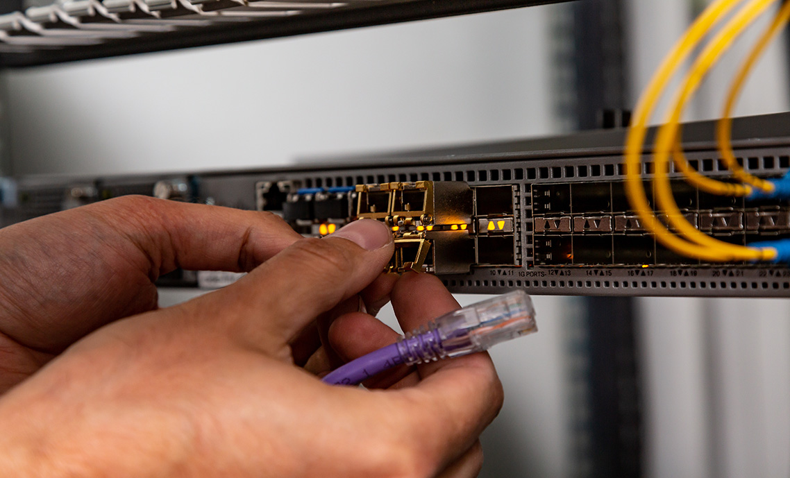
Conversion uses hardware that translates optical signals to electrical signals. Options include standalone media converters, switching converters for rate conversion, SFP transceivers (fiber or copper), and managed switches with both fiber and copper ports. Hardware must match connector types, transmission standards, and speed settings.
Planning Copper‑to‑Fiber Links
What should I check before I commit to a copper‑to‑fiber conversion?
Successful conversion depends on aligning system requirements with environmental and operational constraints. Key considerations include distance, bandwidth, PoE needs, environmental conditions, and labor/tool requirements. Copper supports PoE but is limited to roughly 100 meters; fiber supports kilometers but requires separate power. NEC 2026 applies to support/securement and separation when routing copper and fiber alongside power conductors.
How should I lay out media converters in the network?
Converter topology determines how converters are deployed. Single converters are used when one end is fiber and the other is copper. Paired converters are used when both ends are copper but fiber is needed in between. Integrated switch ports eliminate standalone converters. Topology affects cost, latency, and serviceability.
What is rate conversion latency and when does it matter?
Rate conversion occurs when switching converters adjust link speed between fiber and copper. This can introduce buffering delays and compatibility issues. Applications like VoIP, video, and industrial control may require matched‑speed links. Use pure media converters or matched‑speed transceivers when latency is a concern.
What is wavelength matching and why is it important?
Fiber transceivers operate at specific wavelengths and must be matched across the link. Single‑mode and multimode fiber support different distances and wavelengths. Connector types must match device ports, and duplex/simplex must be correct. Mismatched optics can cause signal loss or link failure.
Compatibility Requirements & Field Troubleshooting
Will my existing devices work after conversion?
Yes—if the conversion hardware matches signal type, speed, and connector format. Compatibility must be confirmed across connector types, transmission standards, speed/duplex settings, wavelength, and firmware. Field testing is recommended to validate performance.
Are there standards I need to follow?
Conversion should align with TIA/EIA‑568 for structured cabling and IEEE 802.3 for Ethernet transmission. NEC 2026 applies to support/securement and separation when copper and power conductors share pathways. Following standards reduces risk and supports long‑term scalability.
What are common troubleshooting issues?
Common issues include signal mismatch, connector contamination or damage, duplex conflicts, unsupported SFPs, and power delivery gaps. Fiber ends may be dirty or reversed; copper connectors may have bent pins. Use certified testers, visual fault locators, and switch diagnostics to isolate faults.
Field Deployment, Supports, and Cable Management
What is environmental durability in conversion environments?
Environmental durability refers to a component’s ability to withstand physical, thermal, and environmental stressors. Industrial‑grade converters operate in extreme temperatures, vibration, and moisture. Enclosures protect against dust and water. Mounting options include DIN rail, wall‑mount, and rack‑mount. Cable jackets must match the environment.
Where is copper‑to‑fiber conversion commonly applied?
Conversion is used wherever high‑speed, long‑distance, or EMI‑resistant connectivity is required beyond copper’s limits. Applications include data centers, industrial automation, campus networks, surveillance systems, healthcare, education, transportation, and smart‑city infrastructure.
How should I manage fiber and copper cables after conversion?
Cable management preserves signal integrity and serviceability. J hooks support horizontal runs for both copper and fiber when bend radius is respected. Bridle rings support copper bundles in open ceilings; saddled variants protect bend radius. Magnetic cable managers support racks and retrofit zones. Fiber routing must respect bend radius and cleanliness. Copper routing must avoid tension and support PoE thermal performance. NEC 2026 requires proper support/securement and separation from power conductors.
This guide delivers the foundational logic and deployment-ready practices required to execute copper-to-fiber conversions with precision, reliability, and full alignment to technical standards.
The information provided in this FAQ is for general informational purposes only and is not intended to replace official codes, standards, or project specifications. Winnie Industries products must always be installed and used in accordance with our product instruction sheets or designated training. Products should never be applied beyond their intended purpose or in a manner that exceeds specified load ratings. Proper fastening is critical to system integrity and functionality, requiring secure attachment to structurally sound components capable of supporting imposed loads. All installations must comply with governing codes, regulations, and job site requirements. Always consult your Authority Having Jurisdiction (AHJ) for specific regulatory guidance.