The Loop That Saves the Pull
Service loops are not an afterthought—they’re a strategic asset in structured cabling design. This guide defines best practices for loop placement, length, hardware integration, and audit readiness across copper, fiber, and coaxial systems. Whether you're planning for future AMCs, protecting terminations, or ensuring compliance with bend‑radius and strain‑relief standards, properly implemented service loops deliver flexibility without compromising signal integrity
Every section below is structured for practical field use, with labeling, inspection, and documentation protocols aligned for both specifiers and contractors.
1. Define the Purpose and Strategic Value of Service Loops
Service loops provide controlled, intentional slack that supports long‑term system reliability and maintenance. They enable adds, moves, and changes without re‑pulling cable, allow recovery from connector damage through re‑termination, act as a buffer for bend‑radius and strain‑relief requirements (especially for fiber and shielded cable), and support inspection or troubleshooting without stressing the cable. Loops must never be used as a corrective measure for poor routing or inaccurate measurements.
2. Apply Proper Placement Zones for Service Loops
Service loops belong only in accessible, code‑compliant locations. Telecommunications rooms can store slack behind patch panels or inside vertical cable managers. Work‑area outlets can house small, neatly organized loops behind wall plates or inside boxes. Ceiling spaces may contain loops only when the cable type matches the environmental rating, and loops must be supported and never rest on ceiling tiles. Equipment racks can store slack near termination points when it does not obstruct airflow or working clearances. Loops must not be placed in riser shafts or inside conduit, as both violate pathway design and fire‑stopping requirements.
3. Determine Loop Lengths by Cable Type
Copper service loops typically require 12–24 inches per end, providing flexibility without creating unnecessary bulk. Fiber loops may require up to 3 meters per end depending on manufacturer guidance, with strict adherence to bend‑radius limits and use of dedicated slack spools. Coaxial loops generally follow copper slack practices but are less common in modern installations. Telecommunications rooms often require additional slack: 1–2 meters for copper and 3–5 meters for fiber, following TIA and BICSI design practices.
4. Integrate Approved Hardware for Loop Management
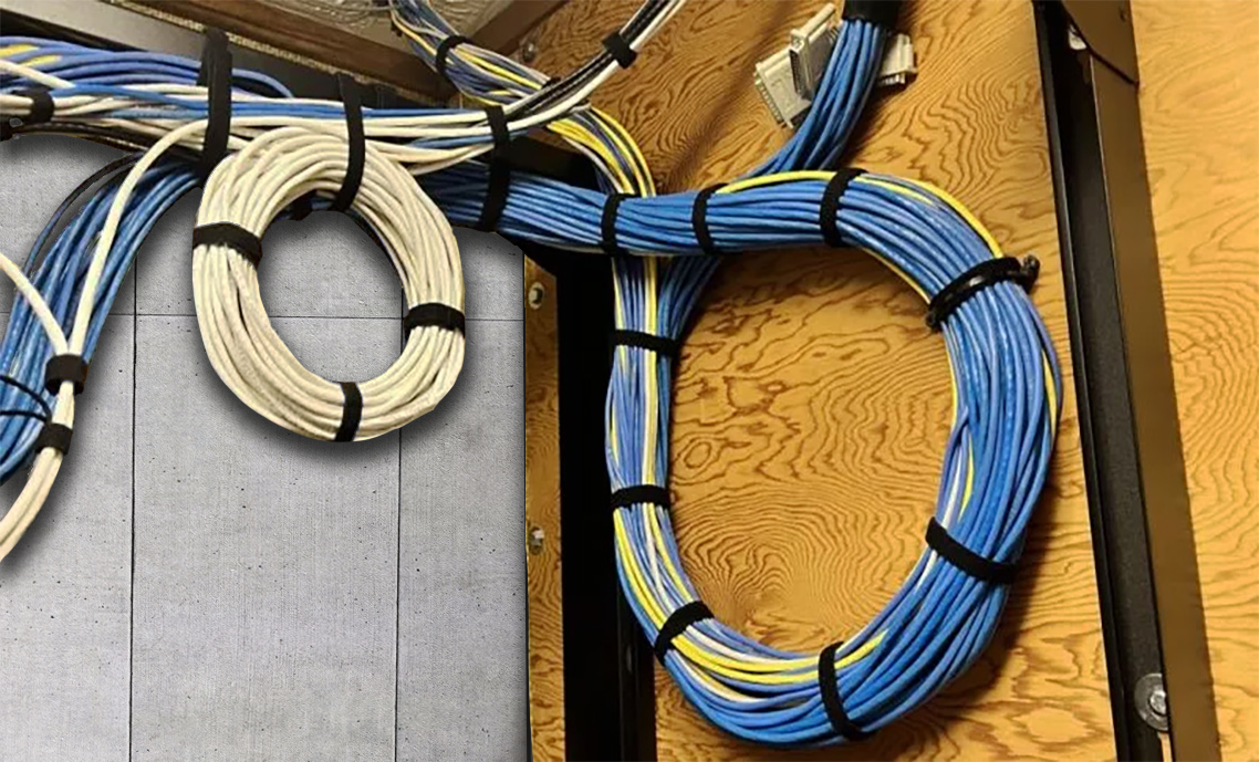
Approved hardware includes hook‑and‑loop straps for non‑abrasive bundling, magnetic cable holders for metal surfaces, distribution rings for vertical or horizontal routing, slack spools for fiber to prevent microbending, j hooks for horizontal support, and cable trays for flat or gently coiled slack. Hardware must support the cable without compression. Avoid cable ties, overstuffed enclosures, unlabeled slack, and any mounting method that risks deformation or violates bend‑radius requirements.
5. Follow Strategic Do’s and Don’ts for Service Loops
Plan service loops during initial layout rather than adding them as a retrofit. Label and document loop locations for future access. Use only approved hardware and maintain separation from power and EMI sources as required by NEC 800.133 and 725.136. Do not treat loops as mistake buffers, overfill trays or boxes, compensate for poor routing with excess slack, or violate bend‑radius or strain‑relief specifications.
6. Apply Field Logic and Sequencing for Loop Installation
Leave slack before final termination and form the loop prior to installing connectors. Audit loop integrity before closing boxes or panels. Document loop length, location, and purpose in as‑built drawings. Apply stricter handling protocols for fiber, including polarity and loss‑budget considerations, and ensure copper loops do not obstruct access or airflow in equipment spaces.
7. Apply Labeling Standards for Service Loops
Labels must be consistent, durable, and traceable throughout the cable lifecycle. A clear format such as “WAO Loop – Cat6 – 18in – Terminated” supports auditing and maintenance. All label details must be incorporated into as‑built documentation.
8. Follow Fiber Loop Handling Protocols
Fiber loops require dedicated slack spools to prevent microbending and maintain bend‑radius compliance. Environmental factors such as temperature must be monitored to preserve fiber integrity. Fiber slack must not interfere with polarity, length budgeting, or connector reach.
9. Manage Loop Density in Pathways and Equipment Spaces
Limit the number of loops in trays or managers to prevent airflow obstruction, thermal buildup, or compression. Loop placement must preserve accessibility for inspection and maintenance and must not obstruct working clearances required by NEC 110.26.
10. Use the Loop Audit Checklist for Quality Assurance
Confirm bend‑radius compliance at every loop. Verify labels match documentation and location plans. Check slack integrity and termination proximity before sealing enclosures. Include visual inspection of loop condition as part of final quality assurance, ensuring loops do not rest on ceiling tiles and do not violate support or separation requirements.
Using service loops is a strategic investment in flexibility, compliance, and long-term cable integrity—ensuring every system remains accessible, auditable, and ready for change.
This guide is intended for informational and reference purposes only. It does not supersede local codes, manufacturer specifications, or the judgment of the Authority Having Jurisdiction (AHJ). Installation practices must always be verified against current NEC, ANSI/TIA standards, and site-specific requirements. Winnie Industries products must be installed and used in accordance with official instruction sheets or designated training. Products should never be applied beyond their intended purpose or in a manner that exceeds specified load ratings. Proper fastening is critical to system integrity and functionality, requiring secure attachment to structurally sound components capable of supporting imposed loads. All installations must comply with governing codes, regulations, and job site requirements. Always consult your AHJ for specific regulatory guidance.